
03.6 Pole Placement (Const Damping and Const Freq Line) s-plane
 |  |
|---|---|
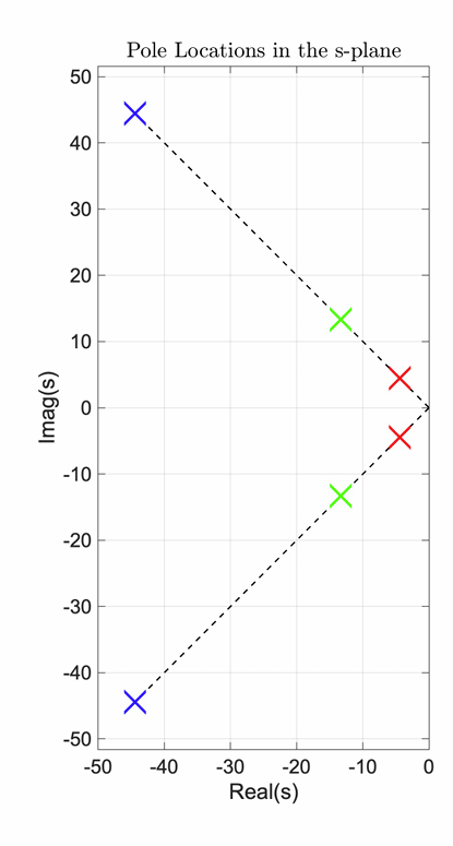
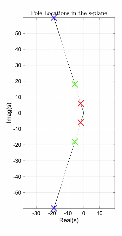
| Fig : Constant Damping Line of $45\degree$ or $\zeta=0.707$ Red = $1 Hz$ Green = $3 Hz$ Blue = $10 Hz$ | Fig : Constant Damping Line of $\zeta=0.3$ Red = $1 Hz$ Green = $3 Hz$ Blue = $10 Hz$ |
| Meaning, across the same line, no matter how far you go, it is the same damping ratio, $\zeta$ | Meaning, across the same line, no matter how far you go, it is the same damping ratio |
| Now, the time constant, $\tau$ depends on the frequency, $\omega$ because $\tau=\frac{1}{\zeta \omega}$ 03.4 Impulse Response Function Plotting | Now, the time constant, $\tau$ depends on the frequency, $\omega$ because $\tau=\frac{1}{\zeta \omega}$ 03.4 Impulse Response Function Plotting |
| That means, blue one is further from the imaginary axis = the most negative real part = faster convergence | In this case, the damping is much less, therefore, all the poles (same $1,2,3 Hz$) are closer to the imaginary axis = longer settling to converge |
| Overshoot depends on the damping ratio only | Overshoot depends on the damping ratio only. Here, we would see that the overshoot would be much higher since the damping ratio is less |
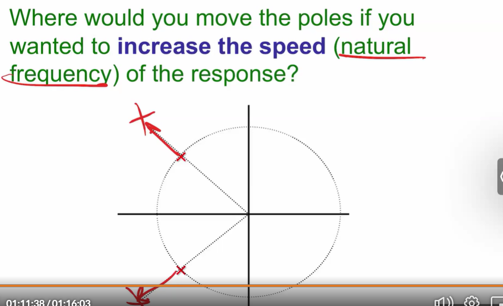
| Changing the radius = Changing the frequency |
 |  |
|---|---|
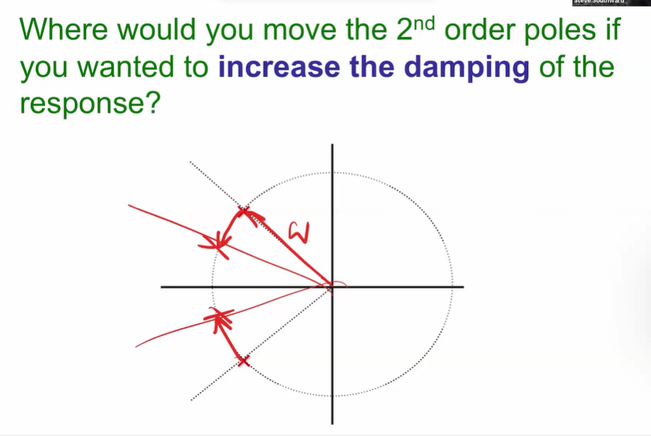
| To increase the damping, I would rotate anti-clockwise because we are keeping the same frequency by making it a constant radius. And we are making it more damped by going away from the imaginary axis | Here, to keep the damping ratio same, i would go along the same radial line. And I would increase the radius, for more frequency, hence, more negative real part, faster response = faster convergence |