
02.2 Closed Loop System with Feedback Control
Block Diagram
We have already learned about a closed-loop system in 02.1 Basics of Closed Loop, where the main idea was to show how we actually close the loop. Pretty self-explanatory enough, right?
Anyway, typically, we feed something back through a control command, like $\mathbf{u}=-\mathbf{G}\mathbf{x}$, into the input. Even though the following diagram may not visually look like a loop, it is still a closed-loop feedback system because we are applying:
\[\mathbf{u}=-\mathbf{G}\mathbf{x}\]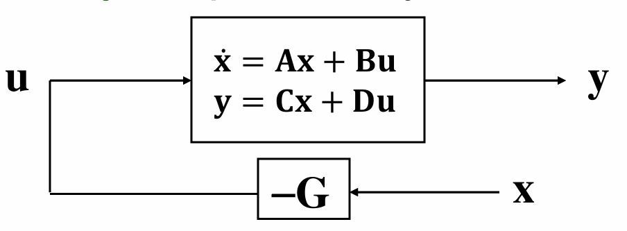
1. Open-loop State-Space System
So we start with the typical open-loop state-space system from 01.1 Basics of Open Loop and 03.1 Creating a LTI Object in MATLAB - Part 1:
\[\begin{aligned}\dot{x} &= Ax +Bu \\ y &= Cx+Du \end{aligned}\]2. Control Law
\[u = -Gx\]3. Final Loop
If we substitute the control law $u = -Gx$ back into the state-space system, we get:
\[\begin{aligned}\dot{x} &= (A-BG)x \\ y &= (C-DG)x \end{aligned}\]Now, this does not look exactly like the canonical state-space form, right? But we can still treat it as a state-space system by defining the new closed-loop matrices like this:
A = A_ol - B_ol * G;
C = C_ol - D_ol * G;
4. Code Snippet
Now, with that:
Acl = Aol - Bol*G_sys;

Ccl = [Col - Dol*G_sys;
       -G_sys];

cl_sys = ss(Acl, [], Ccl, []);

[y,tOut,xOut] = initial(cl_sys, init_vector, t);
Now, we can use initial only to see the initial-condition response of the system. Because in real life, we would usually have an external input too, right? For example, in my ALS final project, I had a reference tracking problem, but in the code above I did not include any external input.
Anyway, one more clarification: the init_vector is just the initial state, not an excitation.
5. Reference
Problem 2 of my ALS final project. However, for the output, you want to plot both the original outputs and the control signals. So I defined it in an augmented way.
A correction or clarification to my Final Project
In your code, you created:
C_augCL = [Col; -G_sys];
D_augCL = [Dol; zeros(2,2)];
Ccl = C_augCL - D_augCL*G_sys;
That is conceptually correct. But then you used:
cl_sys = ss(Acl,[],C_augCL,[]);
Strictly, you should use Ccl, not C_augCL, unless $(D_{ol}=0)$. For your rocket model, $(D_{ol})$ is zero, so it probably gives the same result. But the more correct line is:
cl_sys = ss(Acl, [], Ccl, []);